PRODUCTS
MIS Chip Capacitors
DESCRIPTION
Transcom's MIS Chip Capacitors are available in a wide range of sizes and capacitance values. They are designed to be use as DC blocks coupling filter elements, RF bypass, microwave circuit resonant elements and a fixed capacitance tuning elements in filters, oscillators, and matching networks.
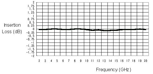
The devices have long-term stability making them suitable for high reliability application. The temperature coefficient is less than 200 ppm/°C, and operation is suitable from –65 °C to 200 °C. Differing from ceramic capacitors,Transcom's MIS Chip Capacitors have high Q and lower insertion loss of 0.1 dB in a 50W system. Insulation resistance is greater than 106 MW.
The wafers are supplied on expanded 6" hoop for high volume automated assembly methods and 100% DC tested to assure consistent quality. Capacitors are packaged in gel packs and 100% visual inspection is always available if required.
DIE ATTACH AND WIRE BONDING
Transcom's MIS chip capacitors are processed with a high quality gold metallization for thermo-compression, thermo-sonic or ultrasonic wire bonding. The top plate of the capacitors is 99.99% sputtered gold with a TiW barrier and typical 3 mm of Au which is suitable for Gold-tin or gold germanium eutectic solders.Epoxy die attach is also acceptable.
ELECTRICAL SPECIFICATIONS
| Capacitance Range | 0.2 to 550 pF |
| Capacitance Thickness | 0.004" ± 0.001" |
| Capacitance Tolerance | ± 20% |
| Operating temperature | -65 °C to 200 °C |
| Temperature Coefficient | 50 ppm/°C Typical |
| Dielectric Withstanding Voltage | 50 V Typical |
| Insulation Resistance | 106 Megohms Typical |
| Leakage Current | Typical < 1nA |
| ROHS Status | Compliant |
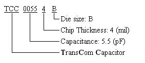
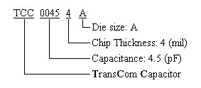
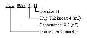
TABLE OF PART NUMBER
| Part Number | Capacitance (±20%,pF) | Chip Type |
| TCCXXXX4A | 0.2 ~ 4.5 | A |
| TCCXXXX4B | 0.6 ~ 13 | B |
| TCCXXXX4C | 3 ~ 50 | C |
| TCCXXXX4D | 1.6 ~ 30 | D |
| TCCXXXX4E | 55 ~ 550 | E |
| TCCXXXX4F | 1 ~ 20 | F |
| TCCXXXX4G | 8 ~ 110 | G |
| TCCXXXX4H | 0.2 ~ 3.7 | H |
| TCCXXXX4I | 2 ~ 27 | I |
| TCCXXXX4Q | 45 ~ 450 | Q |
| TCCXXXX4S | 15 ~ 155 | S |
Any capacitance or chip type not listed here. Please contact Transcom for further information! Thanks!
TYPICAL INSERTION LOSS VS. FREQUENCY (50 pF on 50 ohm system)
PART NUMBER INFORMATION
| Chip type of B,C,D,E,F,G,Q,S | ||||||||||||||||||||||||||||||||||||||||||||||
 Chip type of dimensions (mils)
|
Outline Drowings(mils)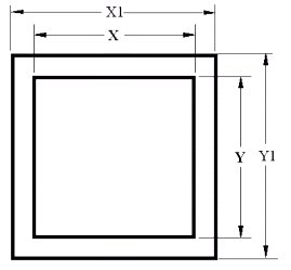 |
|||||||||||||||||||||||||||||||||||||||||||||
| Chip type of A,I | ||||||||||||||||||||||||||||||||||||||||||||||
 Chip type of dimensions (mils)
|
Outline Drowings(mils)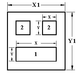 |
|||||||||||||||||||||||||||||||||||||||||||||
| Chip type of H | ||||||||||||||||||||||||||||||||||||||||||||||
 Chip type of dimensions (mils)
|
Outline Drowings(mils)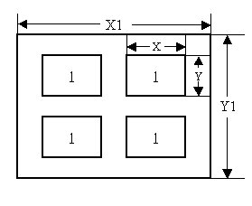 |
|||||||||||||||||||||||||||||||||||||||||||||
MIS CHIP CAPACITORS PRODUCTS SELECTION GUIDE (DOWNLOAD PDF)

OUR PRODUCTS
Based on our PHEMT technology, Transcom has successfully developed product lines of MMICs.